Galaxy Antenna Modification
One of the most popular antennas to mod for use at 2.4 GHz is
the ex-Galaxy TV antenna. The modification described below applies only to the
Galaxy antennas manufactured by the Conifer company. There is an
alternative mod for these antennas; the
Mpot mod. Both 'The
Mpot Mod', and this ('The
RC Mod') work well. Their primary difference is in
mechanical strength of the completed antenna mod. I feel my mod (RC Mod) is more
sound mechanically.
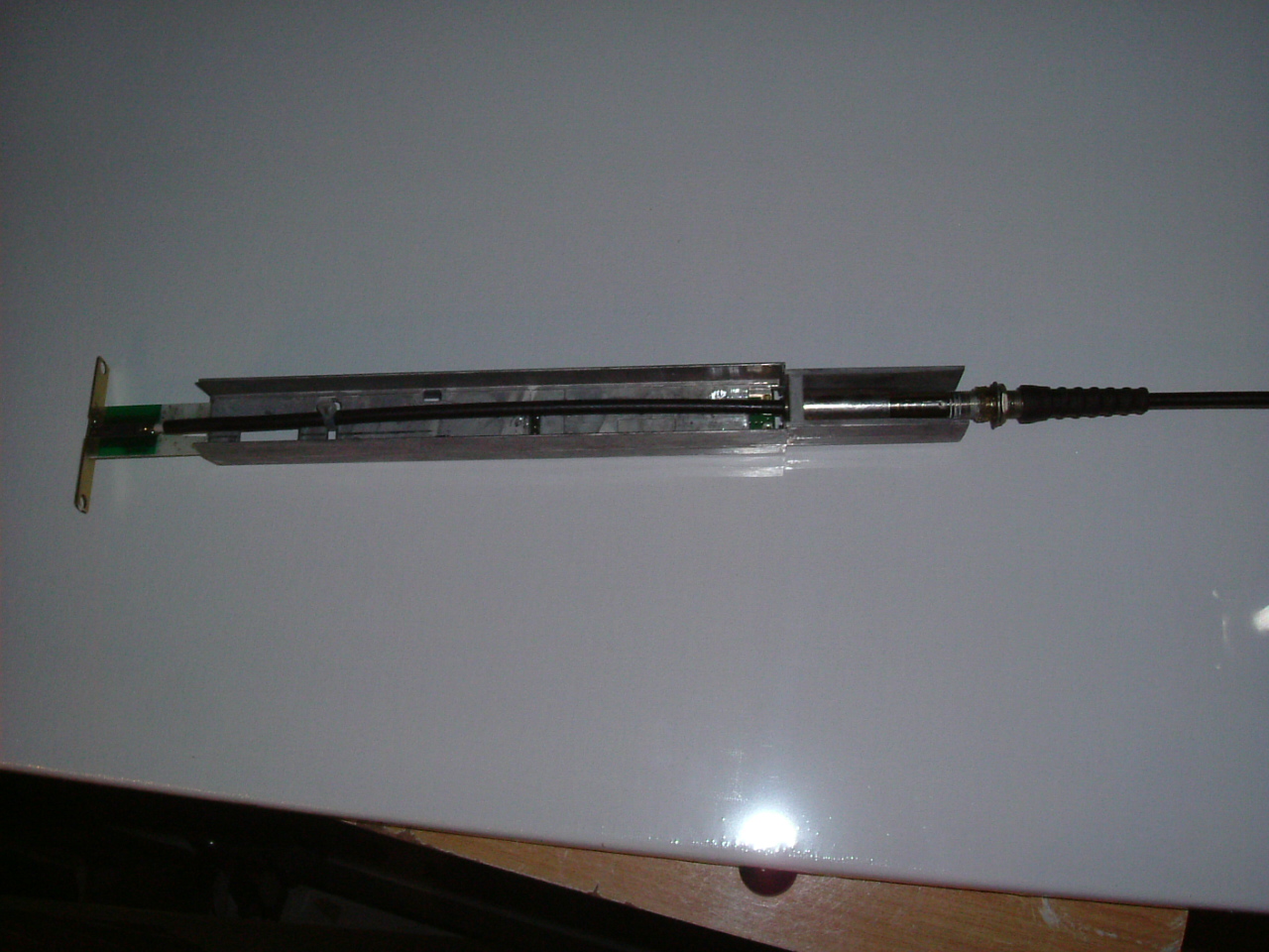
Click on any of the photos here to see full scale.
Step 1 - Disassemble the Antenna and Feed Horn
- Undo the nuts holding the feedhorn onto the grid and the mounting bracket.
- Carefully remove feedhorn. Note: It is easy to break the 'wings' of the
grey metal bracket on the end of the feedhorn.
- Remove the screw on the end-cap of the feedhorn, remove the bent
aluminium sub-reflector.
- Keep the screw and sub-reflector.
- Place the feedhorn on a bench, place a sharp knife blade in along the join
where the end-cap of the feedhorn is glued on, and tap the blade with a
hammer...moving around the feedhorn as you go.
- Undo and keep the nut on the F-connector. Remove and keep the washer.
- Place F-connector on a hard surface and push down on the feedhorn. The
F-connector should slowly disappear inside the feedhorn as the chassis starts
to emerge from the housing.
- Pull chassis out of housing.
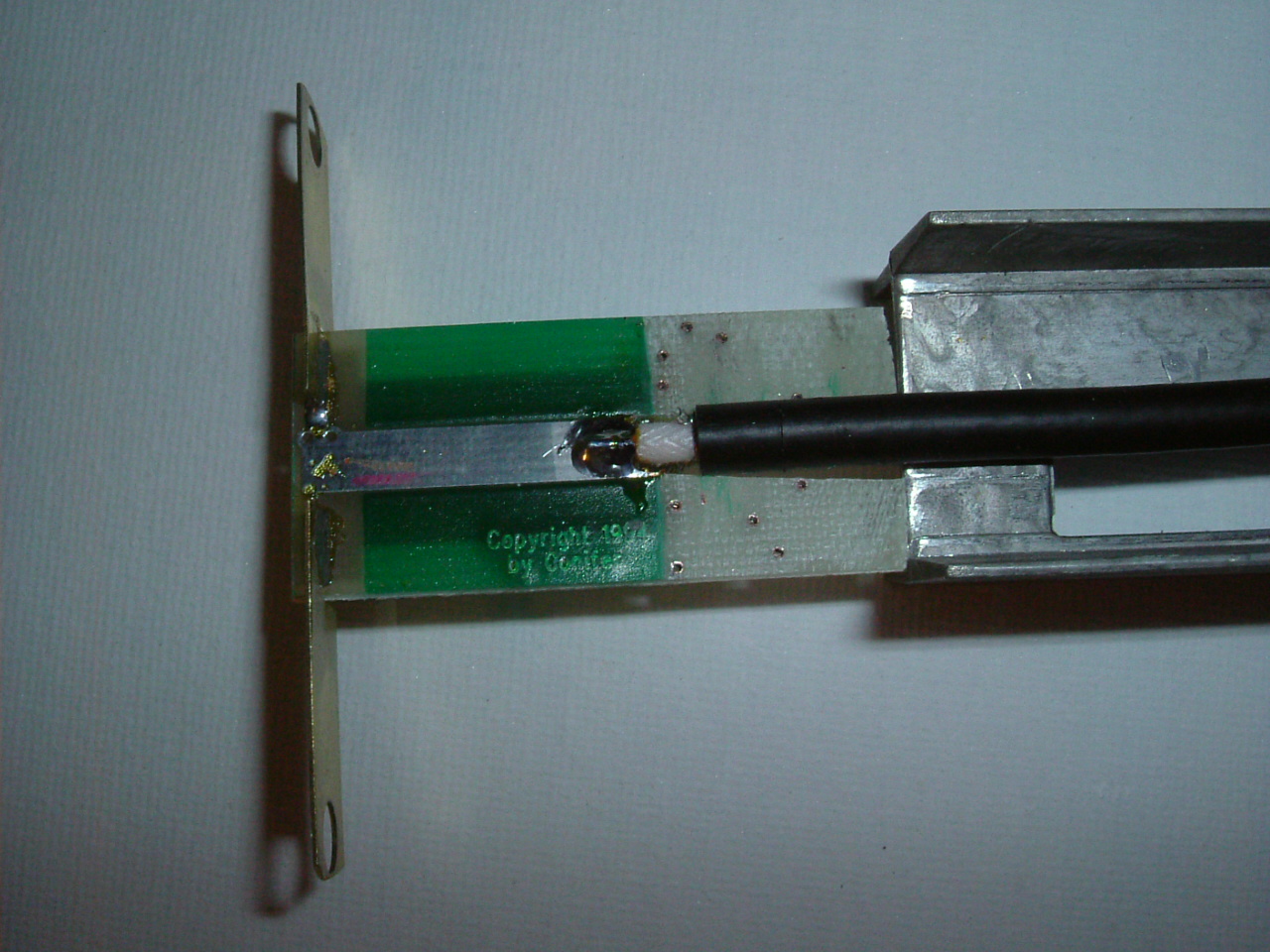
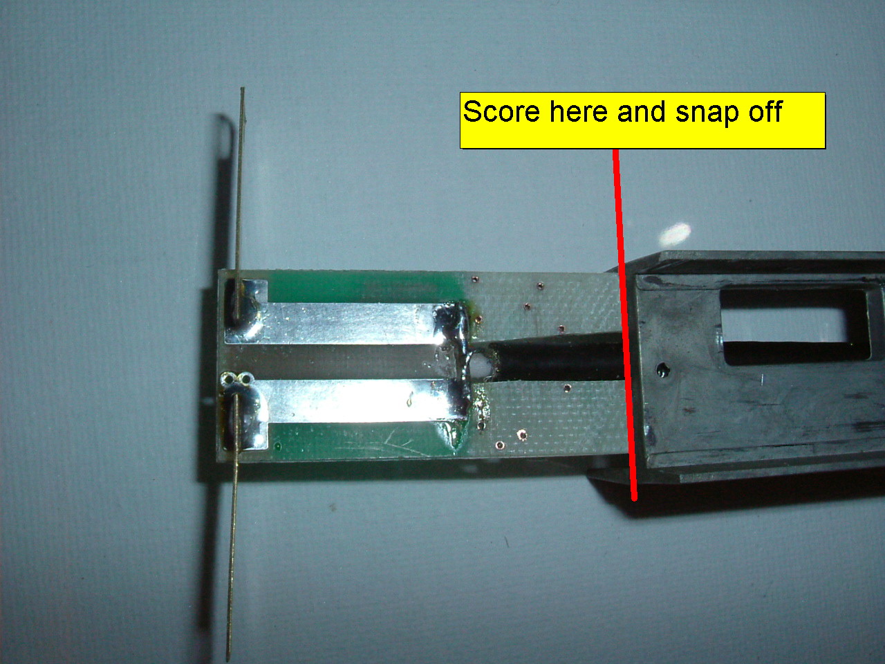
Step 2 - Cut off Dipole
Using a sharp knife, heavily score a line where the printed
circuit board extends from the chassis. The picture below shows the Dipole after
reassembly - but you get the idea.
Step 3 - Remove Circuit Boards from chassis
Simply use a chisel and hammer to remove the chassis boards.
Throw them away.
Also - use an allen key (or pliers) to remove the small bolts
that were holding the chassis in place.
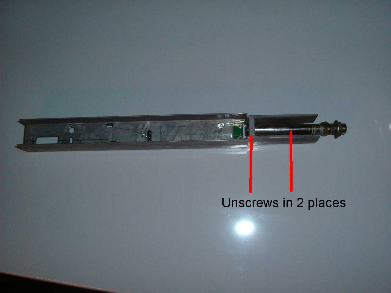
Step 4 - Remove contents of F-connector
The threaded connector at the end of the chassis is called an
F-connector. You must remove the center of that connector, so the CFD200 coax
can pass though. Do not try and drill it out - it will not work.
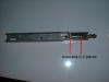
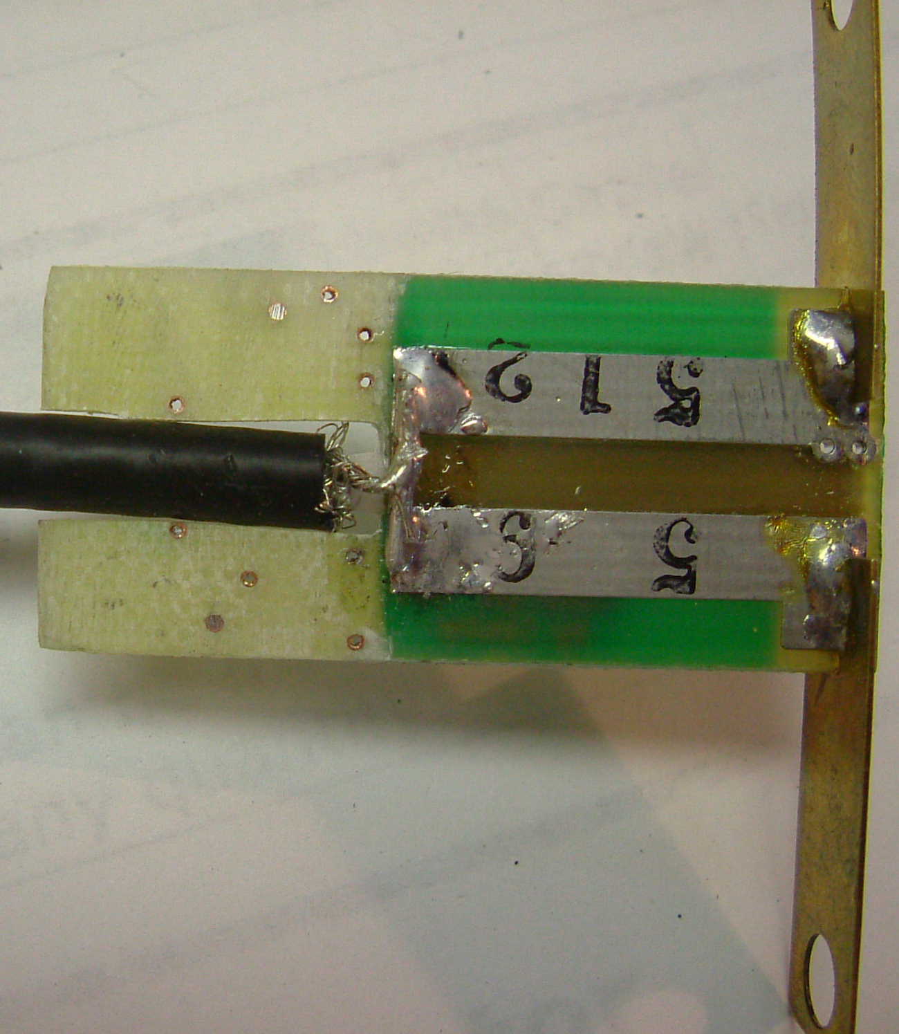
The barrel of the F-connector (right side of the picture) is
comprised of two threaded sections.
- Using pliers, unscrew the barrel from the chassis. It will
come apart at either of the two locations marked with a red line in the above
picture.
- Unscrew from the other red-line location. Your barrel should now be it two
pieces.
- Push out the contents of the barrels.
- Reassemble the barrel.
- Screw barrel back onto the chassis.
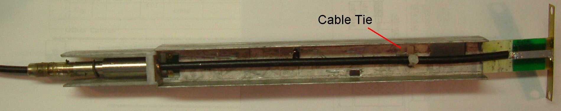
- Drill an extra hole about 1/8" dia at the dipole end of the chassis. In
the picture above, it is the circular hole towards the left end. This hole is
for a cable tie...that we will attach later.
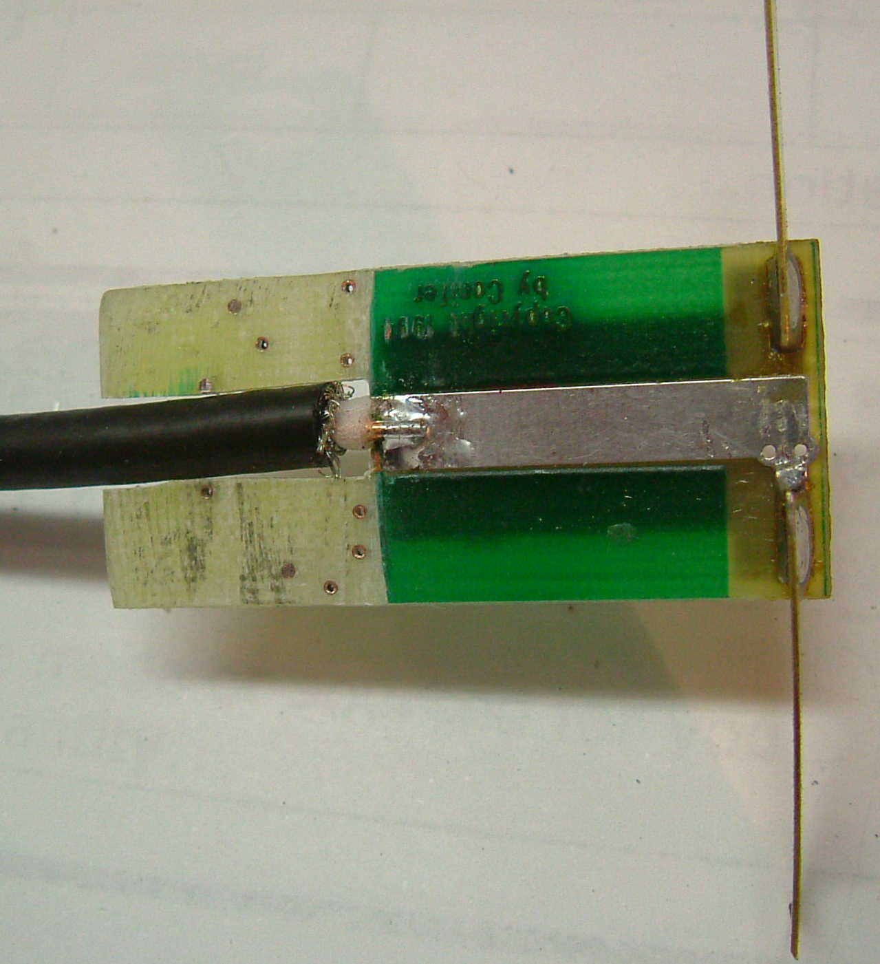
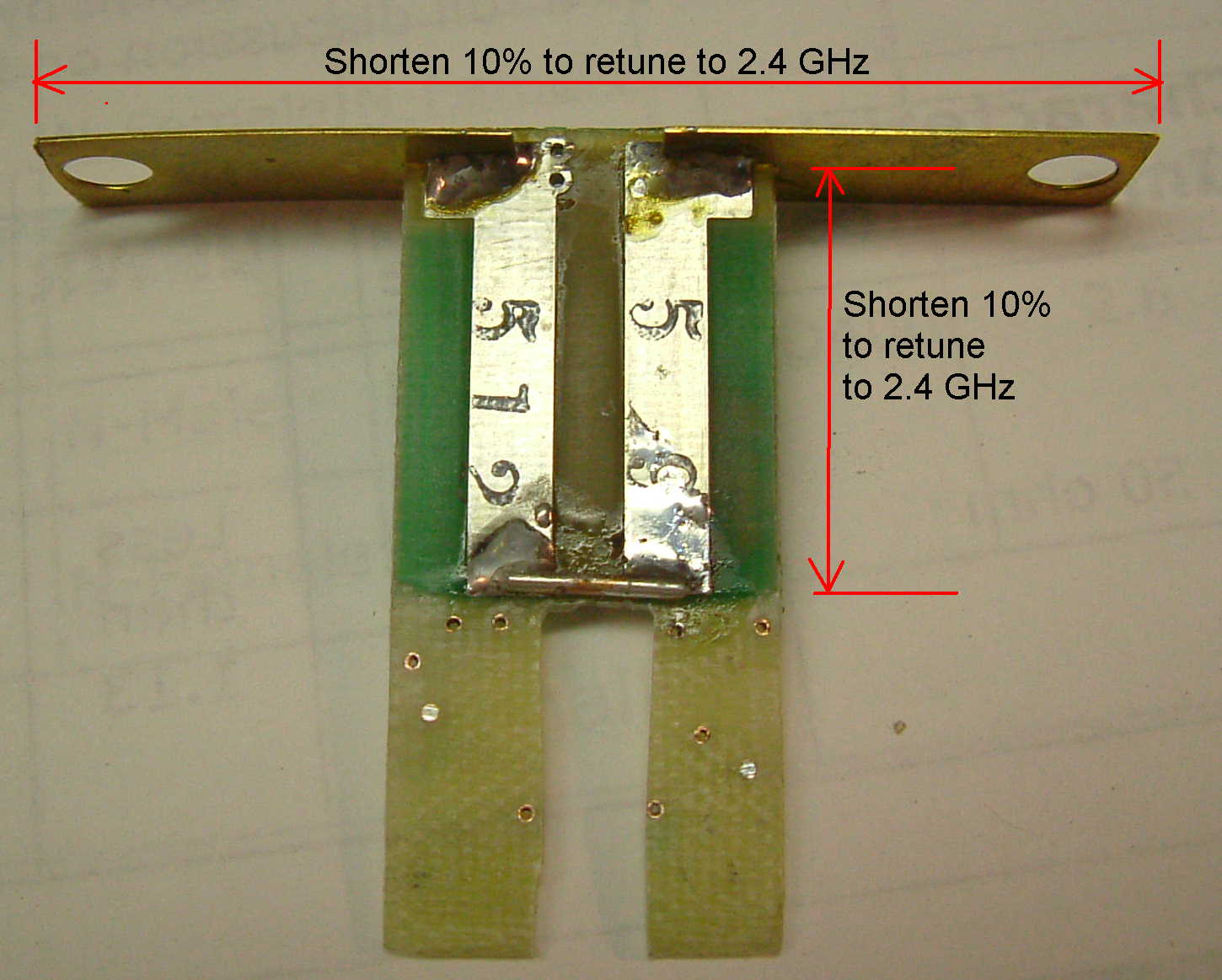
Step 4 - Modify (Re-tune) Dipole
When used for MMDS TV, the dipole is tuned for 2.2 GHz. To
retune to 2.4GHz, we reduce the key dimensions by 10% as shown in this attached
photo.
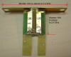
- Shorten the dipole (the horizontal wings in the pictures) by
10%.
- Shorten the length of the balun (the vertical bit in the
pictures) by 10%. Both sides.
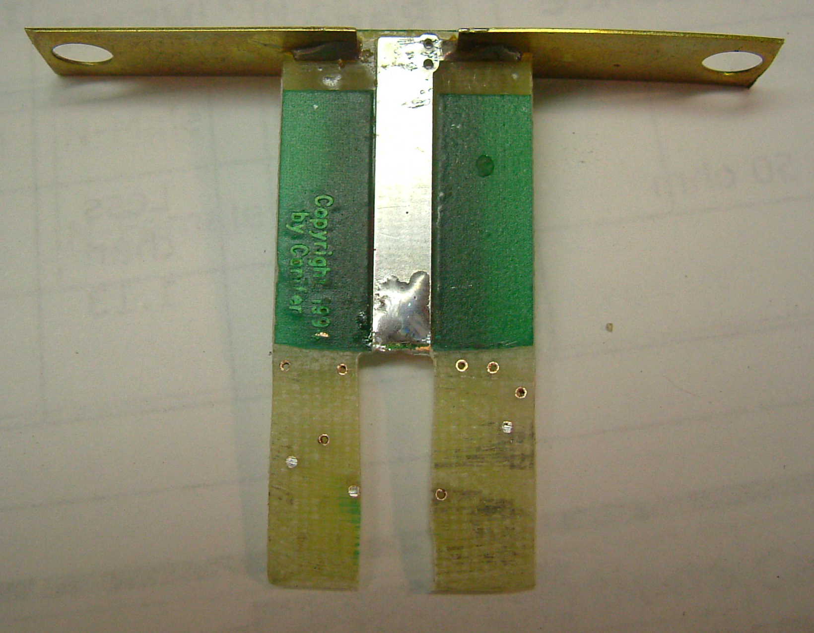
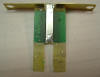
- Use a file or sandpaper to remove all the excess circuit
board track material. Both sides.
- Use a file to create groove below the dipole. It should be
wide enough that the coax cable fits neatly.
- Solder a new shorting bar as shown in the picture. You can use a short
length of copper center conductor from coax. It should be soldered as close
possible to the bottom of the two-legged part of the balun.
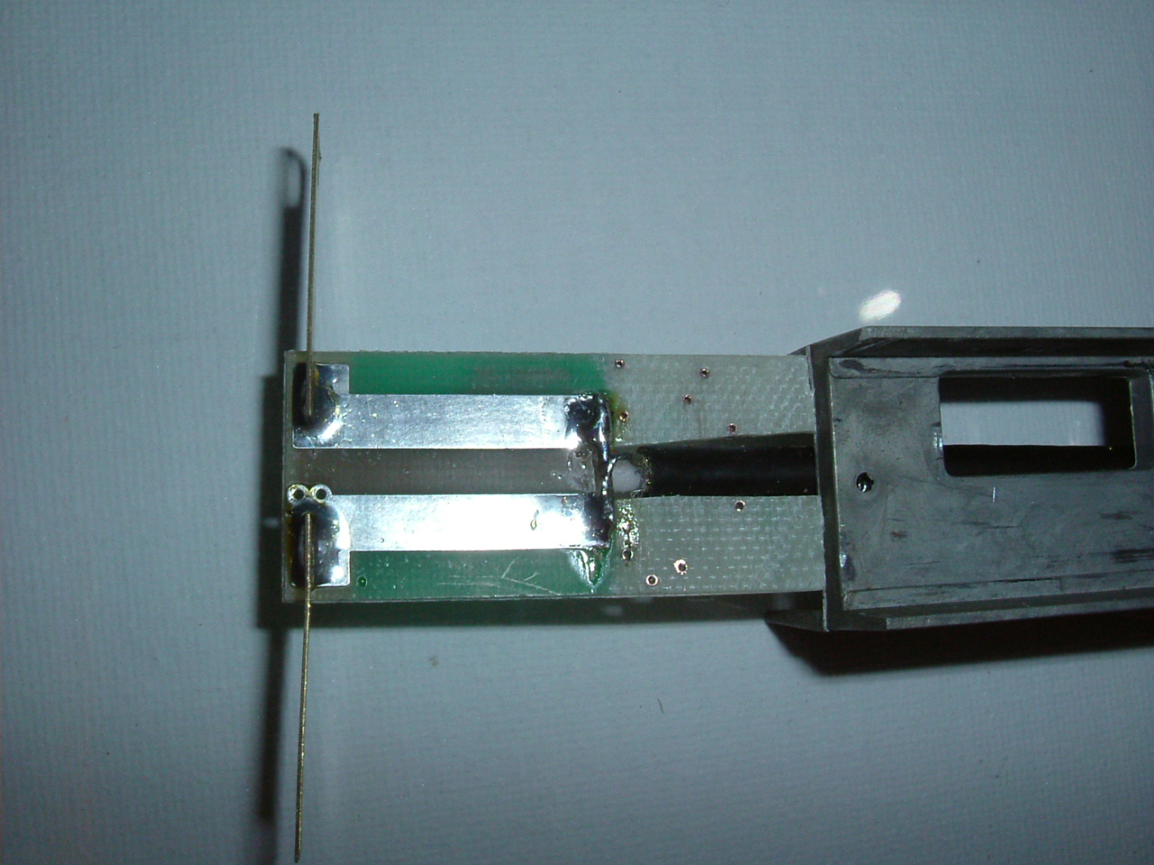
Step 5 - Attach Coax cable
- Pass the bare end of the CFD200 cable though these parts in this order: